
Client
HVMS (on behalf of London Underground)
project name
Wessex CP5 E&P Renewals HV Switchgear Renewals
project value
£500k
date
Feb 2015 to Jan 2016
PROGRAMME DESCRIPTION:
As part of the Network Rail Wessex CP5 E&P Renewals S1&S2 Project, Powersys were commissioned by HVMS to develop the full detailed design package for the This project involved the electrical design for HV switchgear renewals at Waltham and Redbridge Substation as part of the CP5 E&P Renewals, Package S1 & S2. This design was undertaken by Powersys on behalf of High Voltage Maintenance Services Limited (HVMS).
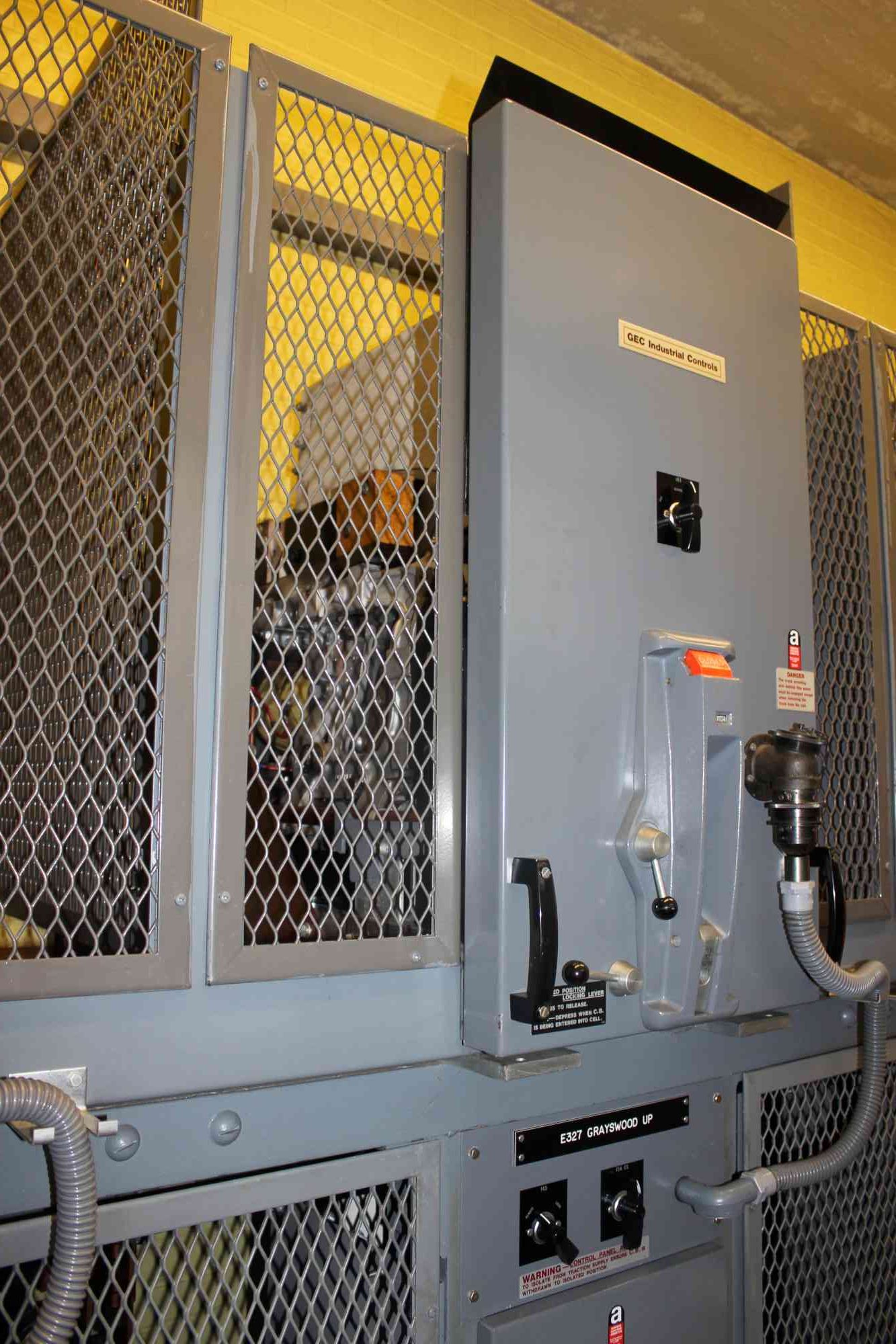
The scope of works covered all E&P works to renew the 33kV switchgear, auxiliary transformer and LVAC changeover panel at the Waltham and Redbridge substation.
PROJECT DESCRIPTION:
The scope of works associated with this package included the following:
- Provision of 33kV Module
- Provision of 33kV / 415V ATs
- Provision of LVAC Changeover Panel
- Interface works including cabling, protection and SCADA
- to existing telecontrol panels and associated connection to upstream and downstream breakers/ points of connection)
- Any associated drawings and manuals.
To create the package to cater for this scope of works, a site visit to ensure all associated on-site drawings were correct was carried out over a full 8-hour period. This was to ensure all aspects of the substation was captured for the associated HV works.
The next step was to liaise with the HV switchgear manufacturer to capture all details of the modern switchgear which will be used at these sites. It was quickly discovered that functionality of the redundant switchgear was quite different to modern plant and as such, modified connections would have to be made to accommodate the new gear. This included, among other innovations, the use of Hot Splice joints to cater for XLPE cabling to be accommodated within an oil filled cable system.
After these tasks were completed, it was envisaged that the following details would need to be provided:
- Multi-phase operational diagram detailing the migration from the existing switchgear to the new units.
- Earthing and bonding schematic
- Earthing and bonding layout
- Block Diagram for the 33kV Cables
- Interface schematics showing the assets to be removed
- Interface schematics for both rectifiers
- Interface schematics for SCADA
- Interface for Pilots to be installed
- Pre-commissioning and post-commissioning electrical layout drawings
- Termination wiring schedules
- HV Protection Report
- LV Calculations
- Hydraulics and Alarms Design Report
- EMC Report
The detail surrounding these deliverables were captured in a design report which detailed all reference documentation detailing philosophy of design and relevant datasheets and technical documentation. Also included was a designer’s risk assessment applicable to the project.
Once this was created, in conjunction with responses from TQs and RFIs, an outline design was created which presented the intention of the design for the client, showing the intention of the modification and the proposed equipment to be used.
This package of works then went for IDC/IDR approval over a 3-hour review with relevant parties from the client’s side and from Powersys. Comments were recorded and any justifiable changes were made to the design package after which the final package was issued to the client.